
Where do we find gears? Better yet, where don’t we find gears? Chances are any machine with a...
A Mechanical Engineers Guide to Drive Systems in Automation
In today’s age of smart manufacturing, industrial automation is transforming how we design and operate machinery. Mechanical engineers are increasingly expected to work alongside automation technologies, especially in the field of motion control. Fundamental to this is a solid understanding of drive systems and the components that enable precise movement in automated machinery.
Whether you're designing packaging machines, CNC systems, or robotic arms, understanding motion control basics and their physical implementations is essential.
Motion control is an area of automation that deals with the precise control of movement, position, speed, and acceleration, of mechanical systems. It’s widely used in manufacturing processes like machining, assembly, and material handling.
A motion control system includes drive systems, actuators (motors), controllers, and feedback devices (sensors).
The Building Blocks of Motion: Drive Systems and Key Components
Drive systems are responsible for converting electrical signals from the controller into mechanical motion. They also regulate power to the motor and often provide protection, feedback interpretation, and communication with higher-level control systems (like PLCs).
Servo Drives, paired with servo motors, offer high-precision control over, position, speed and torque. Applications include robotics, CNC machinery and conveyor systems requiring variable speeds.
Variable Frequency Drives (VFDs) are used to control the speed of AC induction motors by varying the frequency and voltage of the power supply. These drives are energy efficient and feature smooth acceleration/deceleration and overload protection. Often used in applications where speed variation is needed but precise position control isn’t, such as pumps, fans, and compressors.
Stepper Drives are a low-cost-option featuring simple architecture and open-loop control. Operating stepper motors by sending pulse signals that move the motor in discrete steps, this drive system is a perfect solution for low-load automation tasks such as 3D printers and pick-and-place machines.
Other key components in a motion control system include motors, feedback devices, motion controllers, and mechanical transmission elements.
Motors
- Servo Motors: Precision control, high torque, usually with encoders.
- Stepper Motors: Simple and accurate position control in an open or closed loop. Reliable, good torque at low speeds and are low cost.
- DC Motors: Low-voltage DC brushless motors offer flat torque and high power through a wide speed range, quiet operation, reliability, and efficiency in a compact solution. DC brushed motors offer stable and constant operating speed with torque proportional to current. Easy to operate. Commonly used in dispensary equipment, industrial automation, mobility, consumer products and appliances.
- AC Motors: Found in VFD-controlled systems; AC motors are more common in industrial environments – heavy machinery, pumps, and HVAC systems.
- Integrated Motors: Most advanced hybrid stepper motor/drive technology in a single package, providing a new level of motion control capability. Turnkey solution provides simple operation and compact design for industrial automation and lab equipment.
Feedback Devices
- Encoders (Incremental or Absolute): Provide real-time data on position, speed, and direction.
- Resolvers: Rugged, analog feedback devices often used in harsh environments.
Motor (Motion) Controllers
- A Motor Controller is an integrated hardware and software unit that coordinates movement by generating the motion profiles (position, velocity, acceleration).
- Can be standalone or embedded within a PLC.
- Interfaces with HMI, drives, and sensors.
Mechanical Transmission Elements
- Precision Gears, Gearboxes, Ball Screws, and Linear Guides: Translate rotary motion into linear motion or adjust speed/torque.
- Couplings and Belt and Pulley System: Transmit power between components and absorb misalignment or shock.
Integration with PLCs
While motion controllers handle micro-level motion commands, PLCs (Programmable Logic Controllers) are often used for supervisory control, safety, and interlocking logic.
Application Examples
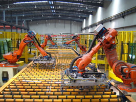
Automated Conveyor System:
A VFD – Variable Frequency Drive controls the speed of an AC motor driving the conveyor belt while photoelectric sensors detect product presence. A PLC triggers the conveyor to start/stop based on sensor input. A touchscreen HMI (Human Machine Interface) allows the operator to monitor and control processes such as adjusting speed setpoints.
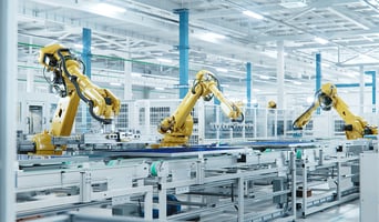
Pick-and-Place Robotic Arm:
This application would require a more advanced system. Servo motors and servo drives would be used with encoders feeding position data back to the controller enabling precision movement and accuracy.
Why It Matters for Mechanical Engineers
As industrial automation continues to evolve, mechanical engineers who grasp the complexities of motion control and drive systems are better equipped to design, innovate, and lead multidisciplinary engineering projects.
Engineering Design and Development: Engineers must select appropriate actuators and drives based on load, speed, duty cycle, and control requirements for various applications.
Effective Collaboration: An understanding of how mechanical and electrical systems interact ensures efficient collaboration with electrical and control engineers leading to better outcomes.
Troubleshooting: Knowledge of drive and motion control systems helps diagnose issues in equipment and devices and allows you to offer impactful problem-solving solutions.
Get Updated on the Latest Trends in Automation
Take some time to better understand the features and benefits of each component and how they can be combined to produce the results needed. Explore white papers, industry articles and attend trade shows and expos to stay ahead of the curve!